A hydraulic manifold is a component that regulates fluid flow between pumps and actuators and other components in a hydraulic system. It could be compared to a switchboard in an electrical circuit, because it lets the operator control how much fluid flows between components of a hydraulic machinery. For example, in a backhoe loader, a manifold turns on or shuts off or diverts flow to the telescopic arms of the front bucket and the back bucket. The manifold is connected to the levers in the operator’s cabin, which the operator uses to achieve the desired behavior. A manifold is composed of assorted hydraulic valves connected to each other. It is the various combinations of states of these valves that allow complex control behavior in a manifold.
Simply put, a hydraulic manifold distributes hydraulic oil throughout a circuit. The flow of pressurized oil is regulated by hydraulic valves installed within the manifold and directed through hoses to some kind of work device, such as a hydraulic motor or a cylinder.
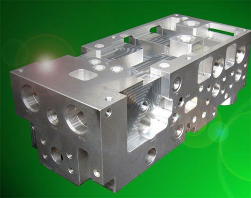
In addition to providing a neat and logical layout, consolidating components into a manifold reduces space, pressure drop, requires less fittings, less assembly time, and reduced leak points. Manifolds are sometimes viewed as a black box, making troubleshooting a concern. However, if a system is properly designed and test points provided in key locations, finding the problem becomes much quicker and simpler. If transducers are connected to these test points, the data may be linked into the machine PLC and even displayed by the HMI.
Typical applications include machine tools, production and material handling equipment, food processing, marine, off-highway equipment, heavy construction equipment, oil field and farm equipment, and valve operations.
Manifolds come in two basic types. One is a mono-block design that holds all the passages and valves for an entire system. The other is a modular-block design. Each modular block usually supports only one or two valves and contains interconnecting passages for these valves as well as flow-through provisions. It normally is connected to a series of similar modular blocks to make up a complete system.
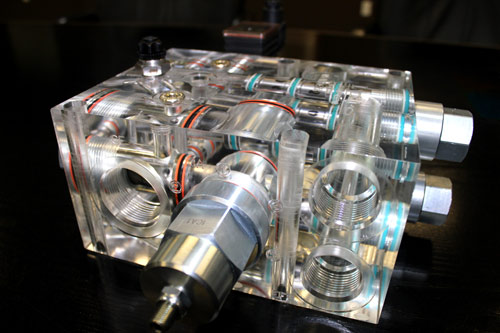
Mono-block manifolds can be either laminar or drilled metal block. Laminar manifolds are usually made of steel, with passages milled or machined through several layers of metal. These plates are stacked or sandwiched with the various fluid paths determined by the shape of the overlapping passages. Solid-metal end pieces are added, and the whole stack is brazed together. These manifolds can handle pressures as high as 10,000 psi. Internal passages can be cut to any shape needed, so nearly any flow rate can be accommodated with minimal pressure drop.
Laminar manifolds are always custom-designed. Valves and other connections can be located where appropriate for a specific application. But because of the permanently shaped flow passages and brazed construction, this type manifold cannot be modified easily if future circuit changes become necessary.
Drilled metal block manifolds are made from plates or bars of steel, aluminum, or ductile iron. As the name implies, the blocks are drilled to provide circuit paths and flow passages. Valves can be placed as desired but the drilled passages must be straight.
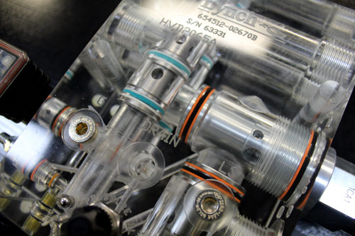
Other drilled-block manifolds accept cartridge valves into cavities drilled into the manifold surface. Interconnecting flow passages travel through the manifold from the valve cavities. Some cartridge valves have threaded bodies that hold them in threaded cavities; others slip into smooth cavities where they are retained by plates on the manifold surface.
Modular manifold systems are easy to modify and can be added to existing manifolds. The blocks are usually made of ductile iron, aluminum, or steel. Blocks can be custom designed or standard. End plates usually seal the ends of the assembled manifold, but these plates also can be drilled for pump and tank connections. Interconnecting, divider, and spacer plates are usually installed between the basic building blocks. Interconnecting plates divert flow from one passage to another between blocks, or stop flow between blocks by plugging a passage. Divider plates allow flow to continue or to be blocked by plugging. Spacer plates increase dimensions between basic blocks when an outsized valve must be accommodated on the mounting surface.

